Cheap charger for Tadiran cells

This is the recipe for making a charger for N Tadiran cells in parallel. It may charge the AA cells as well as the newer 2/3 AA ones.

It's principle is to have N independent current sources, and to monitor the voltages of the N cells by comparing against a reference voltage (3.4 V) provided by a voltage source. When this voltage is reached the cell is disconnected using a simple relay.

Ingredients

For N cells, you will need the following ingredients :

N+1 LM 317
(N for the current sources, plus 1 for the reference voltage)
1 LM324 for 4 cells
(the LM324 contains 4 op amps, which will make the 4 comparators).
N relays, 9V or 12V
(take the cheapest your local dealer has)
N adjustable res, 100 ohm
N res, 220 ohm
(optional)
N LEDs, 220 ohm
(optional)
1 adjustable res, 1k ohm
2 res, 1k ohm
N push switches
(well, I made mine out of paperclips, because it was late and the shops were closed)
1 piece of cardboard
(you make holes in it and plant the components and it looks very professional, too)

A nice schematic (if you can't see it try clicking here or here)

Nice schematic of the charger

The top part is to replicate N times to get a charger for N cells.

How it works

The bottom part is a constant voltage sources, which places at point A the switch-off voltage.

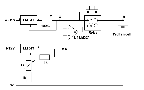
The top part is mainly a constant current source (left). Initially the battery is discharged, so voltage at point B is lower than at point A. You press the pushbutton, which brings this voltage to point C. This brings the voltage at the output of the comparator to a value close to the alimentation, which switches on the relay. You may release the pushbutton. The voltage at point B/C will raise as the battery charges, and when it reaches the voltage at point A, the output of the comparator will go to 0V, which will switch off the relay and stop the charge.

Adjusting and tuning

Most relays can open/close more than one circuit. In this case it is very helpful to have a LED (in series with a 220 ohm resistance) on the other circuit, so that the LED shows when the charge is finished. Maybe it even works to wire this led in parallel with the relay, at the output of the comparator. Who knows.

About the LM317

The LM317 basically maintains a constant 1.25 V between pins 1 and 2.
Hence,

  1/ The current of the current source is given by
     
                            1.25 Volts
            I (Ampere) =  -------------- 
                               Radj
     
  2/ The voltage of the voltage source is given by
                            1k+Radj
	U (V) = 1.25 ( 1 + --------- )
                              1k

The pinout of the LM 317T is as follows:

      ---------                                 _________
      >   O   <                            3   [         ]  2
      ---------                         O------[  LM317  ]------O
      |       |    PIN 1 - ADJUST              [_________]
      | LM317 |                                     |
      |       |    PIN 2 - OUTPUT                   | 1
      ---------                                     |
       #  #  #     PIN 3 - INPUT                    O
       #  #  #

       1  2  3

About the LM324

My favorite quad op amp. It works with a single alimentation.

Here is its pinout (view from top).

    ---0---0---0---0---0---0---0--
   [  4o  4-  4+  gnd  3+  3-  3o ]
   [                              ]
    >                             ]
   [                              ]
   [  1o  1-  1+  VCC  2+  2-  2o ]
    ---0---0---0---0---0---0---0--
   
VCC may range from 3 to 30V.

Back to my Zorglomobile page


Florent de Dinechin
Last modified: Mon Sep 27 09:40:46 MET DST 1999